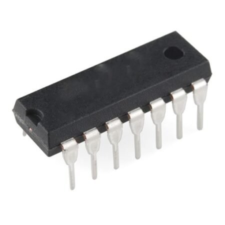
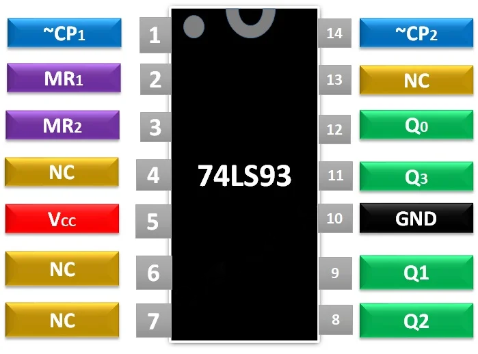
The IC consist of multiple mod counters, The Pin 1 is used to give the pulse to mod eight counter. It’s an active LOW pin.
MR1
Pin 2
Pin 2 is a reset pin used to reset the counter in case of any requirement. It’s an active HIGH pin.
MR2
Pin 3
Pin 3 is the second reset pin used to reset the counter. It’s an active HIGH pin.
NC
Pin 4
Pin 4 is known as NC (no connection) pin which doesn’t have any role in the internal circuit of the IC. It can be used to the PCB for proper support of IC with the board.
VCC
Pin 5
Pin 5 is a power pin used to power up the IC to make it functional.
NC
Pin 6
Pin 6 and Pin 7 are also the NC pins of the IC.
NC
Pin 7
Q2
Pin 8
Pin 8 is an output pin of the IC. The actual output comes in 4 pins and Pin 8 gives the third bit of 4-bit binary data.
Q1
Pin 9
Pin 9 is also an output pin. It gives the second bit of the 4-bit binary data.
GND
Pin 10
Pin 10 is a ground pin. It is used to make the IC ground common with the other compatible devices to make it functional with them.
Q3
Pin 11
Pin 11 is also an output pin. It gives the first bit of the 4-bit binary data.
Q0
Pin 12
Pin 12 is also an output pin. It gives the last bit of the 4-bit binary data.
NC
Pin 13
Pin 13 is also the NC pins of the IC.
~CP0
Pin 14
Pin 14 is the second input pin of the IC. It uses to give the pulse to the mod two counter in the IC. This pin is directly connected to the clock of JK flip flop of Q0.
74LS93 Binary Counter Features
It can be used as a simple 4-bit counter.
It comes in multiple packages with all 14-pins, PDIP.
The clock pulse can be provided by timers such as 555 timers or any microcontroller.
The IC has a faster speed to almost 32MHz.
The output of the 74LS93 counter comes in TTL, which makes it compatible with other ICs and microcontrollers.
Electrical Specifications SPECIFICATIONS
The operating voltage range for IC is 4.5 to 5.5V, but typical Operating Voltages are 5 Volts
The HIGH and LOW states will be represented by voltages on the IC. The HIGH will be represented by 3.5V (min) and LOW will represent by 0.25V (min)
The output for the current will also be different from IC. The HIGH state current will be -0.4mA and LOW will be 8mA
The clock input frequency for CP0 is 32MHz and CP1 is 16MHz
The pulse width for CP0 will be 15ns and for CP1 will 30ns, it will be double also like input frequency
The operating temperature range can also be from 0 to 70 degrees