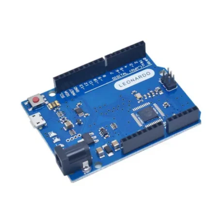


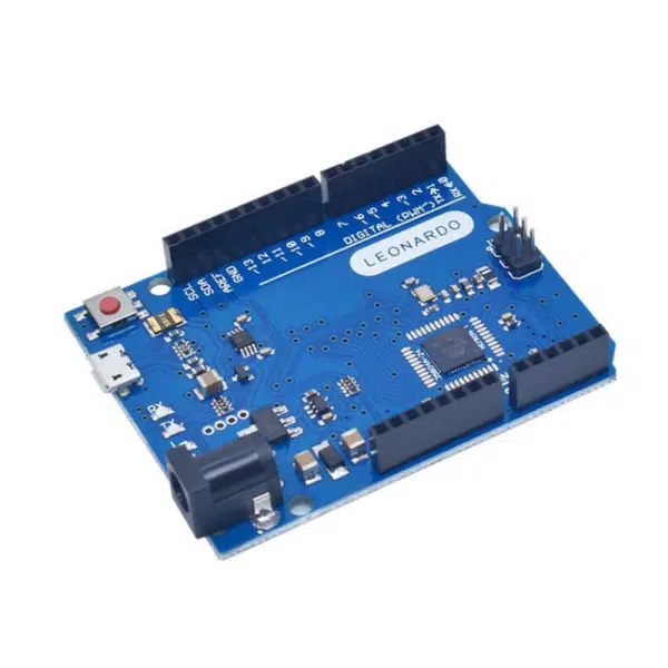
- Arduino Leonardo R3
Arduino Leonardo; It is an Atmega32u4 based microcontroller board. It has 20 digital input/output pins (7 of them can be used as PWM outputs, 12 of them can be used as analog inputs), 16Mhz crystal, micro USB socket, power socket, ICSP connector and reset button.
There is everything necessary for the operation of the microcontroller on the board.
It can be easily connected to a computer via a USB cable, powered by an adapter or a battery.
The biggest feature that distinguishes Leonardo from many other Arduino models is;
It is the internal USB communication feature on the Atmega32u4.
This way there is no need for a second usb-serial converter processor like the 16u2.
In this way, apart from the virtual COM port ( CDC), Leonardo can be used by connecting to the computer as a mouse or keyboard.
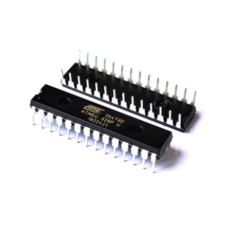
– Microcontroller ATmega32u4
– Operating Voltage 5V
– Input Voltage (recommended) 7-12V
– Input Voltage (limit) 6-20V
– Digital I/O Pins 20 (7 PWM outputs, 12 analog inputs)
– Analog Input Pins 12
– Each Current 40 mA for I/O
– 3.3V Current 50 mA for Output
– Flash Memory 32 KB (ATmega32u4) Up to 4 KB used by bootloader
– SRAM 2.5 KB (ATmega32u4)
– EEPROM 1 KB (ATmega32u4)
– Clock Speed 16 MHz
– Length 68.6 mm
– Width 53.4 mm
– Weight 20 g
Arduino Leonardo can get its power via USB or external power supply. The external power source can be either an AC-DC adapter or a battery. The adapter can be connected from the 2.1mm center-positive power socket on the board. The battery can be connected via the GND and Vin pins on the board.
It is not necessary to have the USB constantly connected for the card to work. The card can only be powered by adapter or battery. In this way, the card can be operated independently from the computer.
It can be used as an external power supply between 6-20V. However, these values are limit values. The recommended external supply for the board is between 7-12V. Because the regulator on the board may not work stably at values below 7V. It can also overheat at values above 12V.
The operating voltage of the microcontroller on the Leonardo board is 5V. The voltage between 7-12V, which is given over the Vin pin or power socket, is reduced to 5V with the voltage regulator on the board and distributed to the board.
The power pins are as follows:
– VIN: Voltage input pin between 7-12V when using external power supply.
– 5V: This pin outputs 5V from the regulator. If the board only works over usb (5V), 5V from usb is output directly over this pin. If power is supplied to the board via Vin (7-12V) or power socket (7-12V), 5V from the regulator is output directly over this pin.
– 3V3: It is the output pin of the 3.3V regulator on the board. Max. It can output 50mA.
– GND: Ground pins.
Memory:
The Atmega32u4 has 32 KB of flash memory ( about 4 KB is used by the bootloader ). It has 2.5 KB SRAM and 1 KB EEPROM.
Input and Output:
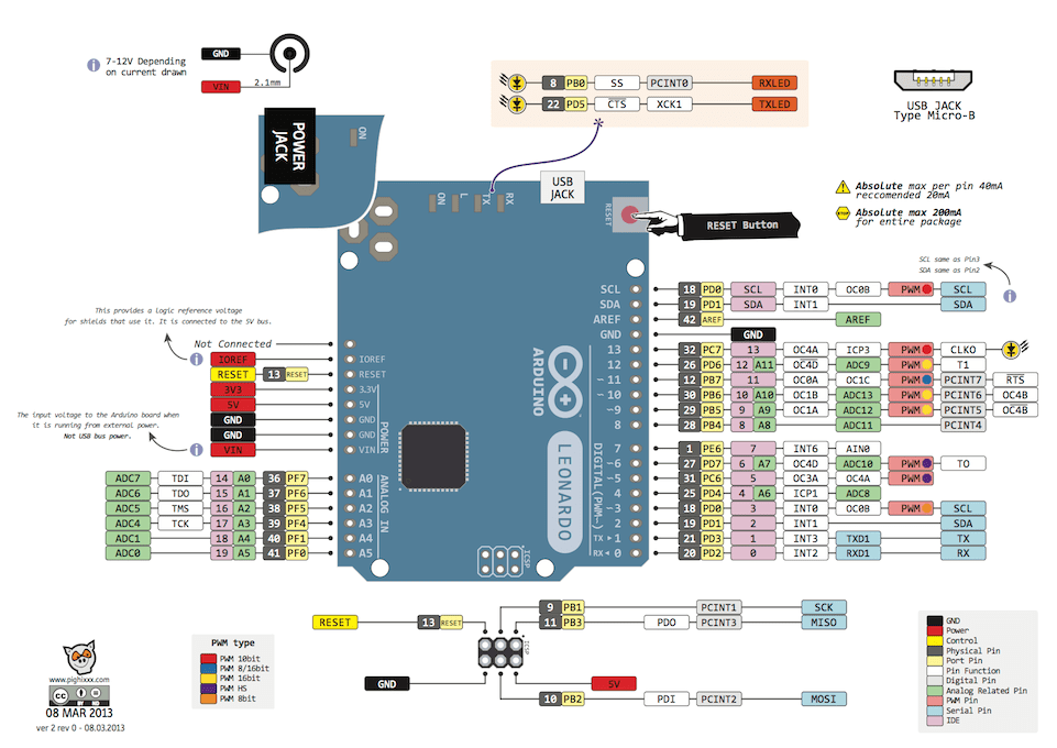
All 20 digital pins on the Leonardo can be used as inputs or outputs. The logic level of all these pins is 5V. Each pin max. It works with 40mA input and output current. In addition, some pins have different properties. Special pins are as follows.
– Serial Communication, 0 (RX) and 1 (TX): TTL Used to receive (RX) and transmit (TX) serial data. The point to be noted is that the Serial class is used for USB (CDC) communication on the leonardo. Serial1 class should be used for serial communication on pins 0 and 1.
– External Interrupt, 3 (interrupt 0), 2 (interrupt 1) , 0 (interrupt 2) , 1 (interrupt 3) , 7 (interrupt 4) : These pins can be used as rising edge, falling edge or change interrupt pins. For detailed information, you can check the attachInterrupt() function page.
– PWM, 3,5,6,9,10,11 and 13: Can be used as 8-bit resolution PWM output pins.
– SPI on ICSP Header: These pins are used for SPI communication. The point to be noted is that the SPI pins on the ICSP header are not connected to any other pins on the board. So these pins are not connected to pins 10,11,12 and 13 as in uno. If you are going to use a shield with SPI communication, this shield must have a 3×2 pin ICSP header. Otherwise this shield cannot be used with leonardo.
– LED, 13: There is an internal LED connected to pin 13 via Leonardo. When the pin is set to HIGH, the led will turn on, and when the pin is set to LOW, the led will turn off.
– Analog, A0-A5 and A6-A11 (also digital pins 4,6,8,9,10 and 12): The Leonardo has 12 10-bit analog input pins. The ones between these pins A0-A5 are in the analog pin part as in the uno. The ones between A6-A11 are on the digital pin part and are connected to the digital pins 4,6,8,9,10 and 12 respectively. These pins are indicated at the bottom of the board. All analog pins can be used in digital input and output. The measuring range of the pins is 0-5V. By using AREF pin and analogReference() function, lower limit can be increased and upper limit can be lowered.
– I2C, pin 2 or SDA and pin 3 or SCL: These pins are used for I2C communication. These pins were connected to the A4 and A5 pins on the uno. On the Leonardo it is connected to pins 2 and 3.
– AREF: Reference pin for analog input.
– Reset: When the microcontroller is wanted to be reset, this pin is set to LOW. Reset operation can also be done with the Reset Button on the card.
You can review the pin mapping page between Arduino Leonardo and Atmega32u4 .
Communication:
There are several different options for Arduino Leonardo to communicate with a computer, another arduino or microcontroller. Atmega32u4 offers UART TTL (5V) serial communication via 0 (RX) and 1 (TX) pins. By connecting to the computer via 32u4 usb, it opens a virtual com port and enables serial (CDC) communication. The Arduino computer program allows text-based information to be sent and received between the arduino and the computer with the serial monitor it contains. When there is communication between Leonardo and the computer via USB, the RX and TX leds on the card will light up.
There is one serial port on the Leonardo as hardware. However, this number can be increased in software with the SoftwareSerial library .
Atmega32u4 also provides I2C and SPI ports. The Wire library that comes with the Arduino computer program is used to use I2C , and the SPI library is used to provide SPI communication.
Leonardo can be introduced to the computer as a mouse, keyboard and can be used with the Keyboard and Mouse classes.
Programming:
The Arduino Leonardo board is programmed with the Arduino computer program (Arduino IDE). You can start programming by selecting Arduino Leonardo under Tools > Board tab in the program. For detailed information, you can review the reference and basic functions page. A special software called bootloader is installed on the Atmega32u4 on the Arduino Leonardo . In this way, you do not need to use an extra programmer while programming the card. Communication is provided with the original AVR109 protocol.
By bypassing the bootloader software, the board can be programmed directly via the ICSP header of the microcontroller with the ISP programmer ( Reference ).
Usb Overcurrent Protection:
The resettable fuse on the Arduino Leonardo protects the USB port of the computer from short circuits or excessive current consumption. When the card draws more than 500mA current through the computer USB port, the card automatically cuts off the power it receives from the USB for protection. When the overcurrent condition or short circuit is eliminated, the fuse returns to its normal position and reconnects.
Atmega32u4 Datasheet
Driver Download Document (Windows)
Board Schematic
Eagle PCB Drawing Files
Arduino Software (Arduino IDE)
Arduino Page