Relay Pin Configuration
| Pin Number | Pin Name | Description |
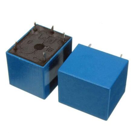
| 1 | Coil End 1 | Used to trigger(On/Off) the Relay, Normally one end is connected to 48V and the other end to ground |
| 2 | Coil End 2 | Used to trigger(On/Off) the Relay, Normally one end is connected to 48V and the other end to ground |
| 3 | Common (COM) | Common is connected to one End of the Load that is to be controlled |
| 4 | Normally Close (NC) | The other end of the load is either connected to NO or NC. If connected to NC the load remains connected before trigger |
| 5 | Normally Open (NO) | The other end of the load is either connected to NO or NC. If connected to NO the load remains disconnected before trigger |
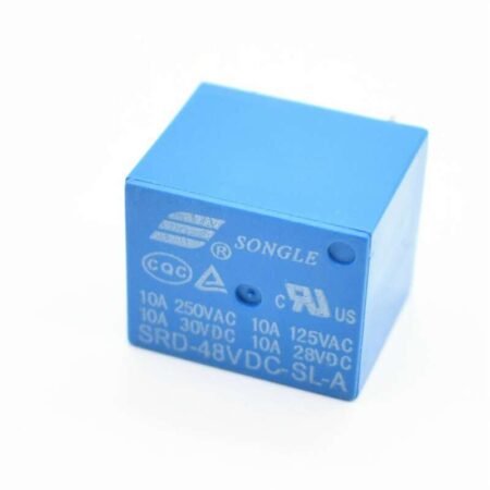
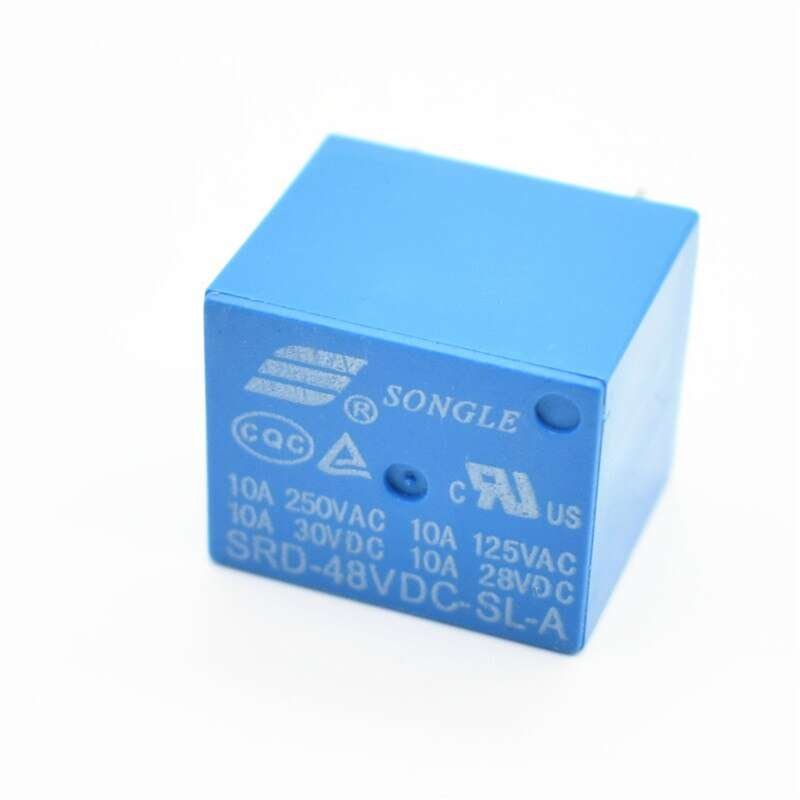
Features of 5-Pin 48V Relay
- Trigger Voltage (Voltage across coil) : 48V DC
- Trigger Current (Nominal current) : 7.5mA
- Maximum AC load current: 10A @ 250/125V AC
- Maximum DC load current: 10A @ 30/28V DC
- Compact 5-pin configuration with plastic moulding
- Operating time: 10msec Release time: 5msec
- Maximum switching: 300 operating/minute (mechanically)
Applications of Relay
- Commonly used in switching circuits.
- For Home Automation projects to switch AC loads
- To Control (On/Off) Heavy loads at a pre-determined time/condition
- Used in safety circuits to disconnect the load from supply in event of failure
- Used in Automobiles electronics for controlling indicators glass motors etc.
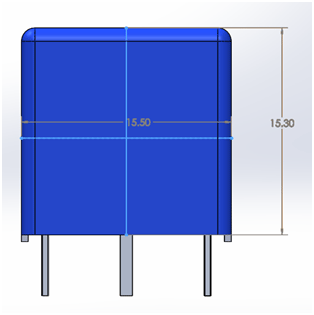
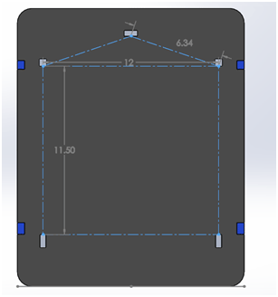
2D model of the Relay
