The MPU-6050 is the latest product of invensense company products. This sensor is used in Ardupilot autopilot. The sensor contains a 3 axis MEMS accelerometer and a 3 axis MEMS gyro in a single chip. It is very accurate, since it contains 16-bits analog to digital conversion hardware for each channel. Therefore it captures the x, y, and z channel at the same time.
Also, it is accurate because you have the 3 axis gyro and 3 axis accelerometers on single chip so you do not need to align them.
The sensor has a “Digital Motion Processor” (DMP), also called a “Digital Motion Processing Unit”. This DMP can be programmed with firmware made by invensense and is able to do complex calculations with the sensor values.
Features
- I2C Digital-output of 6 or 9-axis MotionFusion data in rotation matrix, quaternion, Euler Angle, or raw data format
- Input Voltage: 2.3 – 3.4V.
- Tri-Axis angular rate sensor (gyro) with a sensitivity up to 131 LSBs/dps and a full-scale range of ±250, ±500, ±1000, and ±2000dps.
- Tri-Axis accelerometer with a programmable full scale range of ±2g, ±4g, ±8g and ±16g
- Digital Motion Processing™ (DMP™) engine offloads complex MotionFusion, sensor timing synchronization and gesture detection.
- Digital-output temperature sensor.
How to use the GY-521 module (MPU-6050 breakout board) with the Arduino Uno
The GY-521 module is a breakout board for the MPU-6050 MEMS (Microelectromechanical systems) that features a 3-axis gyroscope, a 3-axis accelerometer, a digital motion processor (DMP), and a temperature sensor. The digital motion processor can be used to process complex algorithms directly on the board. Usually, the DMP processes algorithms that turn the raw values from the sensors into stable position data. This tutorial gives only a brief introduction to the GY-521/MPU-6050. In particular, it is shown how to retrieve the raw sensor values. The sensor values are retrieved by using the I2C serial data bus, which requires only two wires (SCL and SDA). If you plan to use the full range of features or require reliable and stable position data, then I recommend to have also a look at ready-to-use libraries. Please follow this link to find an excellent library with many examples: https://github.com/jrowberg/i2cdevlib/tree/master/Arduino/MPU6050.
List of materials:
– Arduino Uno
– Jumper wires
– Breadboard
– GY-521 module
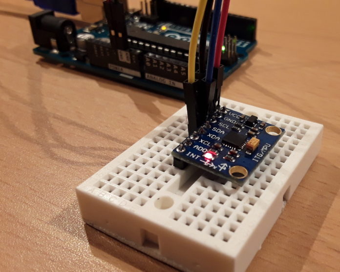
GY-521 Pin Layout
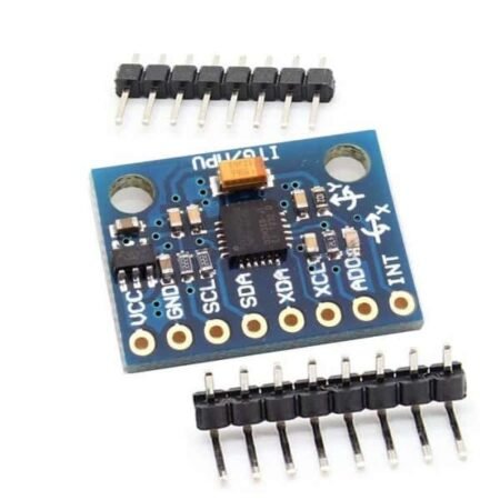
The GY-521 breakout has eight pins:
- VCC (The breakout board has a voltage regulator. Therefore, you can connect the board to 3.3V and 5V sources.)
- GND
- SCL (Serial Clock Line of the I2C protocol.)
- SDA (Serial Data Line of the I2C protocol.)
- XDA (Auxiliary data => I2C master serial data for connecting the module to external sensors.)
- XCL (Auxiliary clock => I2C master serial clock for connecting the module to external sensors.)
- AD0 (If this pin is LOW, the I2C address of the board will be 0x68. Otherwise, if the pin is HIGH, the address will be 0x69.)
- INT (Interrupt digital output)
Wiring layout of GY-521 Example
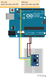
In this tutorial we will make use only of the first four pins: VCC, GND, SDA, and SCL. First, we connect the module’s VCC to the Arduino’s 5V pin. Then, the module’s GND is connected to one of the Arduino’s GND pins.
Next, we have to set up the I2C connection between the module and the Arduino. Most Arduino Uno variants have an SCL and SDA pin. If you have such an Arduino Uno, just connect SCL to SCL and SDA to SDA.
If you can’t find an SCL and SDA pin on your Arduino, you have to use other pins. Unfortunately, you cannot use just any pin. For each type of Arduino, SCL and SDA are tied to different pins:
- Arduino Uno, Arduino Ethernet, Arduino Nano: A4 (SDA), A5 (SCL)
- Arduino Mega2560: 20 (SDA), 21 (SCL)
- Arduino Leonardo: 2 (SDA), 3 (SCL)
- Arduino Due: 20 (SDA), 21 (SCL)
So, if you have an Arduino Uno without SCL and SDL pins, then connect the Arduino’s A4 pin to the module’s SDA pin. Next, connect the Arduino’s A5 pin to the module’s SCL pin.
Source code of GY-521 Example
We make use of the Arduino platform’s in-built library (Wire) to establish an I2C connection between the Arduino Uno and the GY-521 sensor. At the beginning of our source code, the Wire library’s header file is included. Next, we define and declare some variables.
Then, a convert-function is defined. The convert-function makes sure that all sensor values have the same width when they are printed out to the serial monitor later.
In the setup function, a serial connection is established. Moreover, we start our first I2C transmission to the GY-521 board to wake it up from sleep mode.
In the loop function, seven sensor values (3x accelerometer, 1x temperature, and 3x gyro) are requested from the GY-521 module. The MPU-6050 has many registers which can be read. Fourteen of these registers contain the sensor values that we need. As a first step, we tell the GY-521 module where we are going to start reading (“Wire.write(0x3B);”). Then, we request to read 14 registers (“Wire.requestFrom(MPU_ADDR, 7*2, true);”). If you are wondering, why 14 registers are read instead of 7 registers, the reason is quite simple: Each sensor value has a size of 2 byte. As each register has a size of one byte, a single sensor value must be retrieved by accessing two registers. The first register contains the so-called “high byte” and the second register contains the “low byte”. Next, all values are retrieved and printed out to the serial connection. At the end of the loop function, a delay of one second is added in order to avoid flooding the serial monitor with messages.
// (c) Michael Schoeffler 2017, http://www.mschoeffler.de

#include "Wire.h" // This library allows you to communicate with I2C devices.

const int MPU_ADDR = 0x68; // I2C address of the MPU-6050. If AD0 pin is set to HIGH, the I2C address will be 0x69.

int16_t accelerometer_x, accelerometer_y, accelerometer_z; // variables for accelerometer raw data
int16_t gyro_x, gyro_y, gyro_z; // variables for gyro raw data
int16_t temperature; // variables for temperature data

char tmp_str[7]; // temporary variable used in convert function

char* convert_int16_to_str(int16_t i) { // converts int16 to string. Moreover, resulting strings will have the same length in the debug monitor.
sprintf(tmp_str, "%6d", i);
return tmp_str;
}

void setup() {
Serial.begin(9600);
Wire.begin();
Wire.beginTransmission(MPU_ADDR); // Begins a transmission to the I2C slave (GY-521 board)
Wire.write(0x6B); // PWR_MGMT_1 register
Wire.write(0); // set to zero (wakes up the MPU-6050)
Wire.endTransmission(true);
}
void loop() {
Wire.beginTransmission(MPU_ADDR);
Wire.write(0x3B); // starting with register 0x3B (ACCEL_XOUT_H) [MPU-6000 and MPU-6050 Register Map and Descriptions Revision 4.2, p.40]
Wire.endTransmission(false); // the parameter indicates that the Arduino will send a restart. As a result, the connection is kept active.
Wire.requestFrom(MPU_ADDR, 7*2, true); // request a total of 7*2=14 registers

// "Wire.read()<<8 | Wire.read();" means two registers are read and stored in the same variable
accelerometer_x = Wire.read()<<8 | Wire.read(); // reading registers: 0x3B (ACCEL_XOUT_H) and 0x3C (ACCEL_XOUT_L)
accelerometer_y = Wire.read()<<8 | Wire.read(); // reading registers: 0x3D (ACCEL_YOUT_H) and 0x3E (ACCEL_YOUT_L)
accelerometer_z = Wire.read()<<8 | Wire.read(); // reading registers: 0x3F (ACCEL_ZOUT_H) and 0x40 (ACCEL_ZOUT_L)
temperature = Wire.read()<<8 | Wire.read(); // reading registers: 0x41 (TEMP_OUT_H) and 0x42 (TEMP_OUT_L)
gyro_x = Wire.read()<<8 | Wire.read(); // reading registers: 0x43 (GYRO_XOUT_H) and 0x44 (GYRO_XOUT_L)
gyro_y = Wire.read()<<8 | Wire.read(); // reading registers: 0x45 (GYRO_YOUT_H) and 0x46 (GYRO_YOUT_L)
gyro_z = Wire.read()<<8 | Wire.read(); // reading registers: 0x47 (GYRO_ZOUT_H) and 0x48 (GYRO_ZOUT_L)

// print out data
Serial.print("aX = "); Serial.print(convert_int16_to_str(accelerometer_x));
Serial.print(" | aY = "); Serial.print(convert_int16_to_str(accelerometer_y));
Serial.print(" | aZ = "); Serial.print(convert_int16_to_str(accelerometer_z));
// the following equation was taken from the documentation [MPU-6000/MPU-6050 Register Map and Description, p.30]
Serial.print(" | tmp = "); Serial.print(temperature/340.00+36.53);
Serial.print(" | gX = "); Serial.print(convert_int16_to_str(gyro_x));
Serial.print(" | gY = "); Serial.print(convert_int16_to_str(gyro_y));
Serial.print(" | gZ = "); Serial.print(convert_int16_to_str(gyro_z));
Serial.println();

// delay
delay(1000);
}
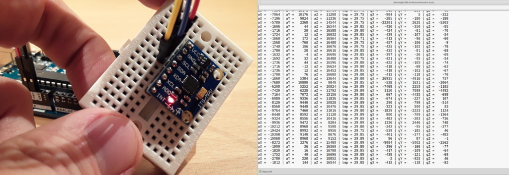
If the code is compiled and transferred to the Arduino Uno, you should see the sensor values in the serial monitor of the Arduino IDE. Moreover, when the GY-521 board is rotated or moved, the sensor values should change according to the movement.
As mentioned before, this is basically a “hello world program” for the GY-521. if you plan to use the board more seriously, I highly recommend to dig deeper into the possibilities of the MPU-6050 MEMS.
