Introduction:
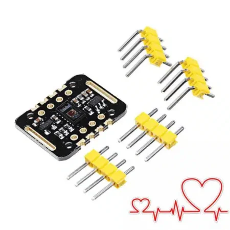
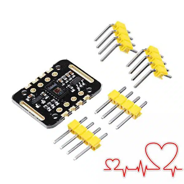
The MAX30102 is an integrated pulse oximeter and heart rate monitor biosensor module. It integrates a red LED and an infrared LED, photodetector, optical components, and low-noise electronic circuitry with ambient light suppression. The MAX30102 features a 1.8V power supply and a separate 5.OV power supply for internal LEDs. It is used in wearable devices for heart rate and blood oxygen acquisition, and is worn on fingers, earlobes, and wrists. The standard 12C-compatible communication interface can transmit the collected values to the Arduino, KL25Z and other microcontrollers for heart rate and blood oxygen calculation. In addition, the chip can also shut down the module through software, the standby current is close to zero, and the power supply is always maintained. Because of its excellent performance, the chip is widely used in the Samsung Gala x y S series mobile phones. Compared with the previous generation MAX30100, the chip integrates a glass cover to effectively eliminate external and internal light interference, and has the best reliable performance.
- LED peak wavelength 660nm/880nm
- LED supply voltage · 3.3 – 5v
- Detection signal type Light reflection signal (PPG)
- Output signal connection · 12C connection
- Communication interface voltage: 1.8, 3.3V, 5V (optional)
- Board reserved assembly hole size: 0.5 × 8.5 mm
Principle Description
- Light-dissolving method: measuring the pulse and blood oxygen saturation by using human tissue to cause different light transmittance when the blood vessel beats;
- Light source: a specific wavelength of light-emitting diode selective for oxyhemoglobin (HbO2) and hemoglobin (Hb) in arterial blood;
- Transmittance is converted into electrical signal: the change of the volume of the arterial pulsation causes the light transmittance to change. At this time, the photoelectrically reflected receiver receives the reflected light from the human tissue and converts it into an electrical signal to amplify and output it.
Pin Description
- VIN: main power supply input, 1.8V-5V;
- 3-bit pad: Select the pull-up level of the bus, depending on the pin master voltage, select 1.8v or 3.3v (this terminal contains 3.3V and above)
- SCL: Clock connected to 12C bus
- SDA: Connect the data of the 12C bus,
- INT: interrupt pin of the MA×30102 chip;
- RD: RED LED ground terminal of MA×30102 chip, generally not connected;
- IRD: IR LED ground terminal of MA×30102 chip, generally not connected
- GND: Ground wire.
Documentation: Demo code of arduino and STM32 please copy from here.
