Product Description
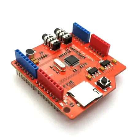
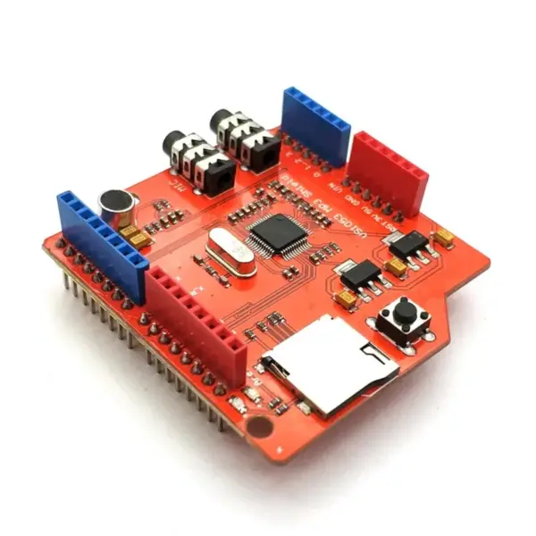
This MP3 Player Shield is an awesome MP3 decoder with the capabilities of storing music files onto a run-of-the-mill microSD card, thus giving you the ability to add music or sound effects to any project. With this board you can pull MP3 files from an microSD card and play them using only one shield, effectively turning any Arduino into a fully functional stand-alone MP3 player! The MP3 Shield utilizes the VS1053B MP3 audio decoder IC to decode audio files. The VS1053 is also capable of decoding Ogg Vorbis/MP3/AAC/WMA/MIDI audio and encoding IMA ADPCM and user-loadable Ogg Vorbis.
The VS1053 receives its input bitstream through a serial input bus (SPI). After the stream has been decoded by the IC, the audio is sent out to both a 3.5mm stereo headphone jack, as well as a 2-pin 0.1″ pitch header.
Features
- Can play a variety of music formats, support for OGG encoding real-time recording
- SPI interface, the control signal lines are led out
- A headphone and stereo output
- A microphone for recording
- A line_in input interface
- Power indicator
- 3.3V and 2.8V of LDO chip AMS-1117 on board, provides up to 800mA current
- A single power supply: +5 VDC
- 12.288 Mhz crystal
- microSD card slot
Decoder formats
- Ogg Vorbis
- MP3 = MPEG 1 & 2 audio layer III (CBR+VBR+ABR)
- MP1 & MP2 = MPEG 1 & 2 audio layers I & II optional
- MPEG4 / 2 AAC-LC(+PNS), HE-AAC v2 (Level 3) (SBR + PS)
- WMA4.0/4.1/7/8/9 all profiles (5-384 kbps)
- FLAC lossless audio with software plugin (up to 24 bits, 48 kHz)
- WAV (PCM + IMA ADPCM)
- General MIDI 1 / SP-MIDI format 0
Encoder formats from mic/line
- Ogg Vorbis with software plugin
- IMA ADPCM
- 16-bit PCM
Instructions
Datasheet for the VS1053 chip (detailed information regarding the audio formats)
We have found that the Adafruit VS1502 Library is the easiest way to use this shield and can be installed directly from the Library Manager of the Arduino IDE

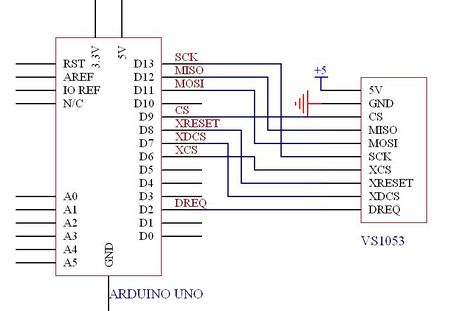
The pinouts for the examples are the following:
#include <SPI.h>
#include <Adafruit_VS1053.h>
#include <SD.h>
// define the pins used
#define CLK 13 // SPI Clock, shared with SD card
#define MISO 12 // Input data, from VS1053/SD card
#define MOSI 11 // Output data, to VS1053/SD card
// Connect CLK, MISO and MOSI to hardware SPI pins.
// See http://arduino.cc/en/Reference/SPI “Connections”
// These are the pins used for the breakout example
#define BREAKOUT_RESET 8 // VS1053 reset pin (output)
#define BREAKOUT_CS 6 // VS1053 chip select pin (output)
#define BREAKOUT_DCS 7 // VS1053 Data/command select pin (output)
// These are common pins between breakout and shield
#define CARDCS 9 // Card chip select pin
// DREQ should be an Int pin, see http://arduino.cc/en/Reference/attachInterrupt
#define DREQ 2 // VS1053 Data request, ideally an Interrupt pin
