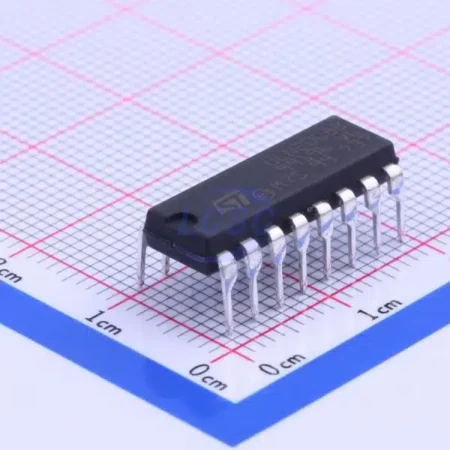


The TDA7388 amplifier, a prominent member of the TDA series developed by STMicroelectronics, has earned its reputation as a versatile and high-performance integrated circuit in the realm of audio amplification.
In this article, we will delve into the pinout configuration, datasheet specifications, and voltage requirements of the TDA7388 amplifier, providing valuable insights for both newcomers and experienced practitioners looking to integrate this amplifier IC into their audio projects.
The TDA7388 is a quad-channel audio power amplifier integrated circuit (IC) designed for use in various audio applications, particularly in car audio systems. It’s manufactured by STMicroelectronics, a semiconductor company. The TDA7388 is known for its ability to drive up to four speakers independently, making it suitable for creating a multi-channel audio experience.
Specification
|
Attribute |
Value |
| REACH Compliance | Yes |
| EU RoHS Compliance | Yes |
| Status | Active |
| Consumer IC | Audio Amplifier |
| Bandwidth Standard | 20.0 kHz |
| Harmonic Distortion | 10.0% |
| JESD-30 Code | R-PZIP-T25 |
| JESD-609 Code | e3 |
| Number of Channels | 1 |
| Number of Functions | 1 |
| Number of Terminals | 25 |
| Nominal Output Power | 26.0 Watts |
| Package Material | Plastic/Epoxy Resin |
| Package Code | SZIP |
| Equivalent Package Code | ZIP25, .16, .16, 40 |
| Package Shape | Rectangular |
| Package Style | IN-LINE, SHRINK PITCH |
| Body Height | 19.37 mm |
| Subcategory | Audio/Video Amplifier |
| Maximum Supply Current | 350.0 mA |
| Mounting Type | Through Hole |
| Technology | Bipolar |
| Terminal Finish | Tin (Sn) |
| Terminal Form | Through Hole |
| Terminal Pitch | 1.0 mm |
| Terminal Position | ZIG-ZAG |
| Length | 29.23 mm |
| Width | 4.5 mm |
Features
- Four Output Channels: Powers up to four speakers, ideal for multi-channel audio setups like car sound systems.
- Low Distortion: Delivers high-quality sound with minimal distortion for clear audio output.
- Low Output Noise: Minimizes unwanted noise for a crisp listening experience.
- Standby and Mute: Includes standby and mute functions for easy control and power efficiency.
- Wide Bandwidth: Reproduces a broad range of frequencies with a standard bandwidth of 20.0 kHz.
- Harmonic Distortion: Maintains low harmonic distortion levels (10.0%) for accurate sound reproduction.
- Package Type: Comes in a 25-terminal ZIP25 package.
- REACH and RoHS Compliant: Complies with environmental and safety standards.
- Bipolar Technology: Utilizes bipolar technology commonly used in audio amplifiers.
- Consumer Electronics: Designed for applications in consumer electronics, especially audio amplification.

|
Pin No. |
Pin Name |
Pin Function and Description |
| 1 | TAB | Connect to Ground: Ground reference point for the chip. Connect to system ground. |
| 2 | P-GND2 | Power Ground of Channel 2: Ground reference for power supply of Channel 2. |
| 3 | OUT2- | Inverting Output of Channel 2: Inverted output signal for Channel 2 audio. |
| 4 | ST-BY | Stand-by: Control pin for standby mode of the amplifier. |
| 5 | OUT2+ | Non-Inverting Output of Channel 2: Non-inverted output signal for Channel 2 audio. |
| 6 | VCC | Supply Voltage: Positive supply voltage (+Vs) input for the chip. |
| 7 | OUT1- | Inverting Output of Channel 1: Inverted output signal for Channel 1 audio. |
| 8 | P-GND1 | Power Ground of Channel 1: Ground reference for power supply of Channel 1. |
| 9 | OUT1+ | Non-Inverting Output of Channel 1: Non-inverted output signal for Channel 1 audio. |
| 10 | SVR | Supply Voltage Rejection: Input for supply voltage rejection circuitry. |
| 11 | IN1 | Input of Channel 1: Positive input signal for Channel 1 audio. |
| 12 | IN2 | Input of Channel 2: Positive input signal for Channel 2 audio. |
| 13 | S-GND | Signal Ground: Ground reference for input and output signals. |
| 14 | IN4 | Input of Channel 4: Positive input signal for Channel 4 audio. |
| 15 | IN3 | Input of Channel 3: Positive input signal for Channel 3 audio. |
| 16 | AC-GND | AC Ground: Ground reference point for AC-coupled input signals. |
| 17 | OUT3+ | Non-Inverting Output of Channel 3: Non-inverted output signal for Channel 3 audio. |
| 18 | P-GND3 | Power Ground of Channel 3: Ground reference for power supply of Channel 3. |
| 19 | OUT3- | Inverting Output of Channel 3: Inverted output signal for Channel 3 audio. |
| 20 | VCC | Supply Voltage: Positive supply voltage (+Vs) input for the chip. |
| 21 | OUT4+ | Non-Inverting Output of Channel 4: Non-inverted output signal for Channel 4 audio. |
| 22 | MUTE | Mute: Control pin for muting the audio output. |
| 23 | OUT4- | Inverting Output of Channel 4: Inverted output signal for Channel 4 audio. |
| 24 | P-GND4 | Power Ground of Channel 4: Ground reference for power supply of Channel 4. |
| 25 | HSD | No Connection: This pin is not connected and has no specified function. |
The amplifier circuit depicted employs the TDA7388 IC, as illustrated in the TDA7388 datasheet. Notably, this circuit stands out due to its ability to accommodate four output speakers simultaneously, a distinctive trait of this amplifier IC.

Furthermore, the TDA7388 boasts exceptional attributes such as remarkably low distortion levels and minimal output noise. An intrinsic feature of the amplifier component is its integrated standby and mute functions, enhancing its operational versatility.
The TDA7388 amplifier typically operates with a supply voltage in the range of 8 to 18 volts. This voltage range allows the amplifier to efficiently power the connected speakers and produce the desired audio output. It’s important to provide a stable and appropriate supply voltage within this range to ensure optimal performance and prevent potential damage to the amplifier circuit.
Input Voltage:
- The input voltage refers to the voltage level of the audio signals that you feed into the amplifier’s input channels (IN1, IN2, IN3, IN4).
- The input voltage range is typically within standard audio signal levels, which are often around 0.1V to 2V for line-level inputs.
- Make sure the input voltage doesn’t exceed the specified maximum input voltage to prevent distortion or damage.
Output Voltage:
- The output voltage of the TDA7388 refers to the voltage level of the amplified audio signals at the amplifier’s output channels (OUT1+, OUT1-, OUT2+, OUT2-, OUT3+, OUT3-, OUT4+, OUT4-).
- The amplified output voltage will depend on the input signal level, gain settings, and the impedance of the connected speakers.
- It’s important to note that the amplifier’s output voltage should be compatible with the speakers you’re using to avoid damaging them or causing distortion.

TDA7388 Symbol

TDA7388 Footprint

TDA7388 3D Model
|
IC Model |
Channels |
Features |
Application |
| TDA7388 | 4 | Low distortion, low output noise, standby/mute | Car audio, multimedia |
| TDA7377 | 4 | High power, low distortion, bridge mode support | Car audio, multimedia |
| TDA7850 | 4 | Built-in diagnostics, protection, high power | Car audio, multimedia |
| LM3886 | 1 | High power, low distortion, audio quality | Audio amplification |
| TDA7560 | 4 | High power, low distortion, diagnostics | Car audio, multimedia |
| TDA1557Q | 4 | DC volume control, low distortion | Car audio, multimedia |
The TDA7388 amplifier is commonly used in:
- Car Audio Systems: Powers multiple speakers for immersive in-car sound.
- Home Audio: Enhances small stereo systems or multimedia speakers.
- Portable Speakers: Boosts audio quality and volume in portable devices.
- Gaming Consoles: Improves gaming audio for a better experience.
- Multimedia Devices: Elevates audio output in TVs, DVD players, etc.
- Amplified Instruments: Applies to electronic instruments like keyboards.
- Public Address Systems: Used for small-scale public speaking setups.
- DIY Audio Projects: Popular choice for custom amplifier builds.
- Educational Labs: Teaches audio amplification concepts.
Check and Download TDA7388 datasheet>>