
The Traffic Light LED Module has large Red, Yellow and Green LEDs arranged in a standard traffic light pattern with built-in current limiting resistors.
Key Features of Traffic Light LED Module:
- Large 8mm Red, Yellow and Green LEDs
- LEDs active HIGH
- Built-in current limiting resistors
- 3.3 and 5V compatible
This module includes large 8mm Red, Yellow and Green LEDs arranged like a typical traffic light that are useful for experimenting with traffic signals, using them on a railroad model or as some type of good/caution/bad status indicators for a project.
The modules have current limiting resistors built-in, so they can be connected directly to the pins of an MCU. You can even plug it directly into the female header of most Arduino boards where you have 3 digital pins next to a ground, such as using the Uno pins 11, 12, 13 & Gnd. The LEDs are lit when a logic HIGH is applied to the pins.
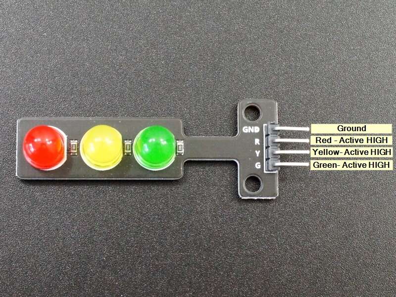
Module Connections
1×4 Header
- G = Green LED, active HIGH
- Y = Yellow LED, active HIGH
- R = Red LED, active HIGH
- GND = Ground
OUR EVALUATION RESULTS:
It is pretty common to do a traffic light setup at some point, even if it is just to play with the software logic of it all. These help take those efforts to the next level and are useful for general indicators such as coupling with the soil moisture sensor to show the status of the plant soil moisture.
The program below uses two of the modules to implement a typical 2-way traffic light. It uses a simple state machine to control the LEDs. The state machine is incremented by monitoring the elapsed time using the millis() function. This allows the microcontroller to be off doing other things when it is not busy updating the lights.
The state machine is set to increment every 2 seconds and calls the UpdateLights function each time it increments. The Switch Case statement only takes action on states 0,4,5 and 9. The other states are ignored so the last state remains in effect. This allows us to set the delay between the different states. A Green and Red light cycles take 4 states (8 seconds), while the Yellow light cycle only lasts 1 state (2 seconds).
You can hook up the LEDs to any 6 digital pins, we use 4-9 in our example here.
Technical Specifications
| Ratings | ||
| Vcc | 3.3 – 5V | |
| ITyp | 8-9mA @ 5V | |
| Dimensions | L x W (PCB) | 56mm x 13mm |