DESCRIPTION
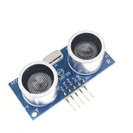
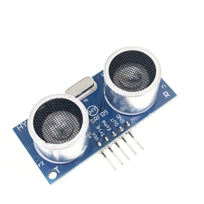
The HY-SRF05 Ultrasonic Range Finder Module uses ultrasonic sound waves to detect the presence of and measure the distance to objects in front of it.
PACKAGE INCLUDES:
- HY-SRF05 Ultrasonic Range Finder Module
KEY FEATURES OF HY-SRF05 ULTRASONIC RANGE FINDER MODULE:
- 2cm -450cm (15 feet) detection range
- 40 kHz operation
- ±15 degree field of view
- 5V operation
- Sensor angle: <15o
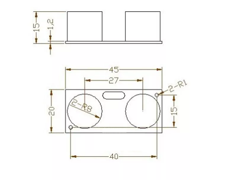
- Dimensions: 45x20mm
The detection and measurement range is from 2 cm up to 450 cm which is about 15 feet with a stated accuracy of ± 2mm. The ultrasonic sound is pulsed at 40 kHz and is not audible to the human ear. The HY-SRF05 is a higher precision version of the HC-SR04, but otherwise is similar in functionality.
These modules are commonly used on robotic vehicles for obstacle detection and avoidance. Because they use sound waves for detection they are not sensitive to light sources or optically reflective surfaces like IR can be. In addition, by using sound instead of light, it is possible to measure the time that it takes for the sound to be echo’d back and therefore the distance to the object can be calculated with a fair amount of accuracy which can be quite handy.
The modules have a ‘view’ of about ±15 degrees, so they are sometimes mounted to a servo motor so that the sensor can ‘look-around’ at its surroundings. The fact that the sensors look like a couple of eyes adds to the cool factor as well.
The way the HY-SRF05 Ultrasonic Range Finder Module works is as follows:
- The module is normally idle.
- A 10uSec or wider logic HIGH pulse is sent to the TRIG pin on the module, usually by a microcontroller. This will cause the module to start a detection cycle.
- The module emits eight bursts of 40KHz sound and sets it’s ECHO pin output HIGH.
- When the signal is reflected back from an object and is detected by the module, the ECHO pin is set back to LOW.
- By measuring the amount of time that the ECHO pin is held HIGH, the distance to the object can be calculated using the basic formula (Time that ECHO is held HIGH * Speed of sound / 2) The divide by 2 is because the sound has to travel in both directions (both out and back) and we want to know just the out distance.
If an echo is not returned (no object detected or signal is blocked), the module will still lower the ECHO pin after a fixed delay. This delay may vary, but is about 200mSec on the modules that I have measured. This is required to prevent the module from hanging if there is no return echo. If you run the test software shown down below and then block the sensor with your hand , you will see what is returned when no obstacle is detected. This is typically something along the lines of 110 feet. To be safe, it is generally best to assume that any reading over about 15 feet is the same as no obstacle being detected.
The speed of sound varies a bit with the air temperature, so for maximum accuracy the air temperature can be measured and used to calculate the current speed of sound, but it is not required for basic collision detection purposes.
Module Connections:
There is a 5-pin header on the assembly. The GND pin is connected to the system ground and the Vcc pin is connected to 5V. The TRIG pin is an input pin on which a 10uSec pulse is applied to start the measurement cycle. The ECHO pin is an output pin that is held HIGH for the duration of the time from when the module sends a 40KHz pulse out until it receives the echo back. The OUT pin is not used.
1 x 5 Header
- VCC – Connect to 5V.
- TRIG – Trigger Input – Connect to any digital output pin on MCU. A 10uSec or wider pulse starts a measurement cycle
- ECHO – Echo Output – Connect to any digital input pin on MCU. This pin is held high for the duration of the the measurement cycle.
- OUT – Not used
- GND – Connect to system ground. This ground needs to be in common with the MCU.
