
Description:
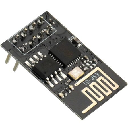
The ESP8266 ESP-01 is a serial WiFi breakout module with a built-in ARM microprocessor that has 1MB of memory and 2 GPIOs brought out to the header for connecting to peripherals. It can be used as a serial to WiFi bridge to add WiFi capability to a project or it can even be programmed directly and used as a little stand-alone processor. It has full TCP/IP capability built-in.
Key Features of ESP8266 ESP-01 WIFI MODULE:
- 32-bit RISC Tensilica Xtensa LX Processor running at 80MHz
- 1MB Flash Memory
- IEEE 802.11 b/g/n WiFi
- 2 GPIO
- 3.3V Operation
The module requires 3.3V for power and is not 5V tolerant on its pins. If connecting to a 5V MCU, the RX pin of the ESP-01 module which is driven by the TX pin from the MCU should have a level shifter installed. This can just be a simple voltage divider using 2 resistors as shown down below. If you are using it with our ESP-01 adapter, the adapter includes level shifting as well as a 3.3V regulator, so it makes the ESP-01 module plug-and-play.
The module has a red power LED and a blue LED to indicate data flow. The WiFi antenna is the meandering PCB trace that covers the end of the module.
The ESP8266 in the name refers to the 32-pin Espressif IC on the module. These chips are quite capable and support up to 16 GPIO. The ESP-01 is the most basic and least expensive implementation of this chip with limited GPIO and is best used for adding WiFi to an existing Arduino or similar MCU board. If you are looking to use it as a stand-alone device, you will typically be better off starting with something like the NodeMCU or ESP32 that we sell which includes all the features of a full microcontroller like the Arduino and can be programmed directly from the Arduino IDE.
From the factory, the modules are loaded with “AT” firmware and can be programmed via a simple terminal program. If you are using the module primarily to exploit its WiFi capabilities and are controlling it with another MCU like an Arduino, that may be all that you need.
If custom software is programmed onto the device, it can be programmed using the Arduino IDE but it will require the use of an FTDI USB to Serial interface.
The module has a 2×4-pin header on the assembly. See the pic for the layout as the boards may not have the pins labeled.
Connection
The module has 8 pins output on the two-row (2×4) gold pin strip raster 2.54 mm.

| PIN | DESCRIPTION |
|---|---|
| Vcc | Power supply 3.3 V, current consumption up to 300 mA. |
| GND | The mass of the system. |
| Tx | The transmitter of the serial interface UART. |
| Rx | The receiver of the serial interface UART. |
| RST | Reset system – activated by low state. In a mode of regular operation, specify high state 3.3 V. |
| CH_PD | Power down – indicating low state causes a transition to sleep mode.
For software updates and communication via the UART, you must specify the high state 3.3 V. |
| GPIO0 | Lead GPIO number 0.
To update software, you must indicate the low status (connect to GND). |
| GPIO2 | Lead GPIO number 2. |
Specifications:
- Supply voltage: 3.3 V
- The working voltage of leads: 3.3 V
- Current consumption up to 300 mA
- Supports standard wi-fi – wi-fi 802.11 b, g, n
- Operates in the 2.4 GHz frequency
- Supports WPA / WPA2 protection
- Can work in AP mode (Access Point), STA (standalone) and AP+STA
- Transmitter power: 19,5 dBm
- Supports AT commands
- Has a built-in Flash memory: 1 MB
- Communication via the serial UART interface
- Has a built-in PCB antenna
- Equipped with communication interfaces: SPI, UART, SDIO
- Has 8 leads pitch of 2 mm
- 3 x GPIO – digital outputs/inputs
- Mounting: through the hole – pitch 2,54 (gold pin connectors)
- Dimensions: 24 x 14 mm